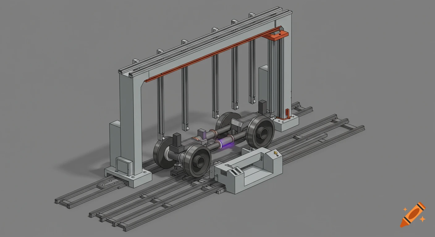
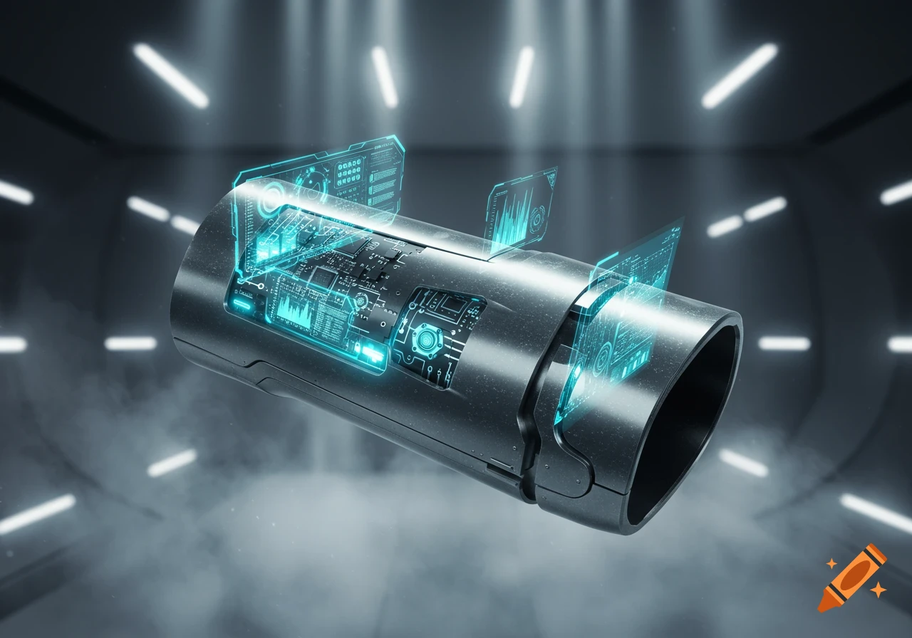
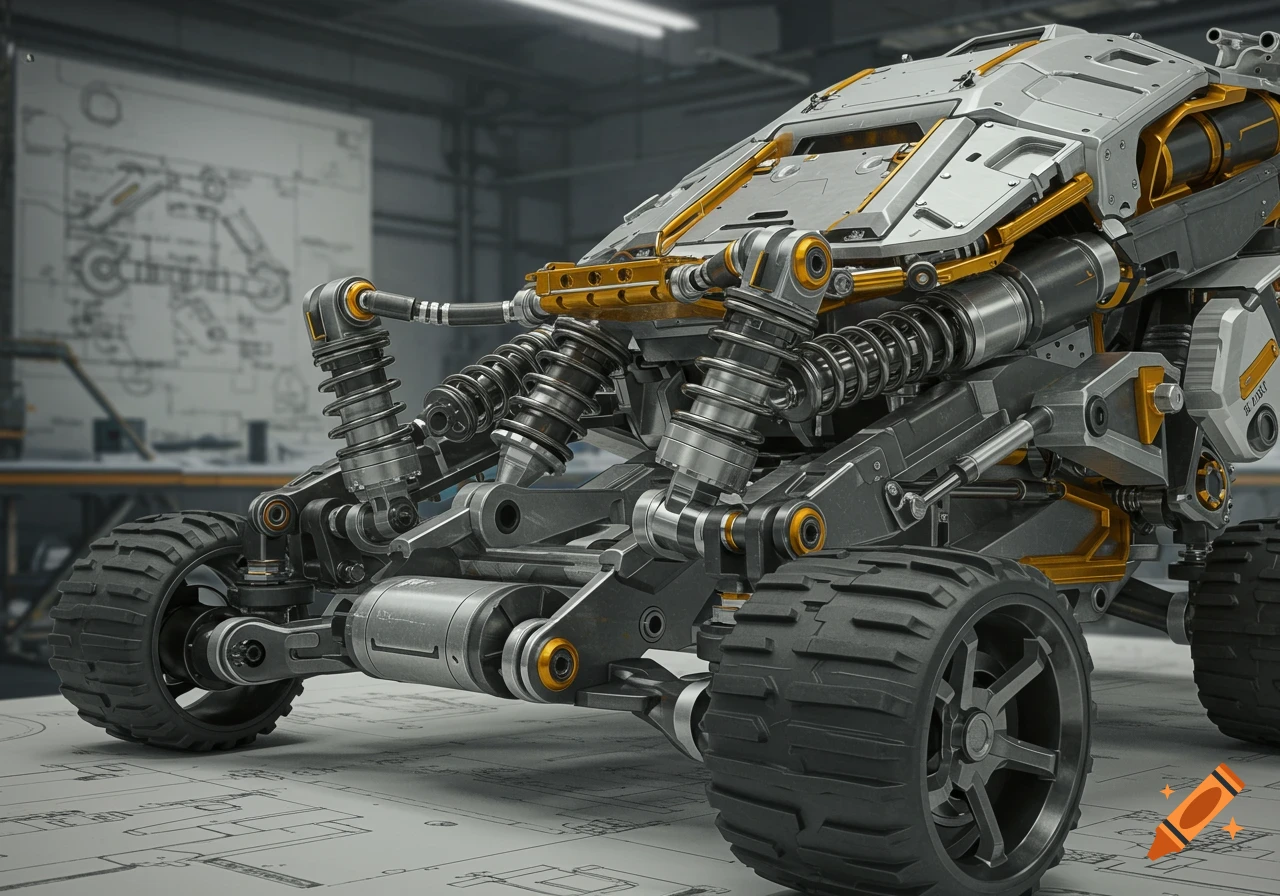
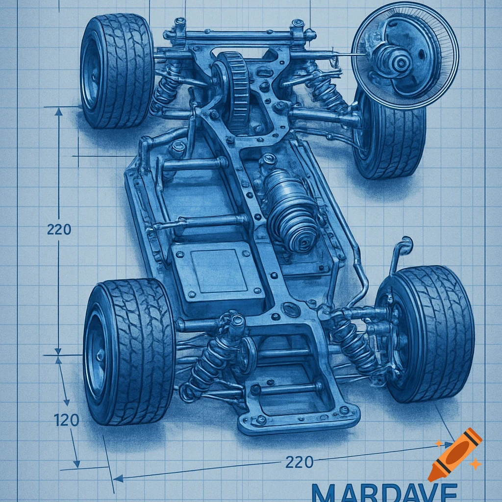
3D engineering concept design of an autonomous external pipe inspection robot with four wheels and detailed technical labels.

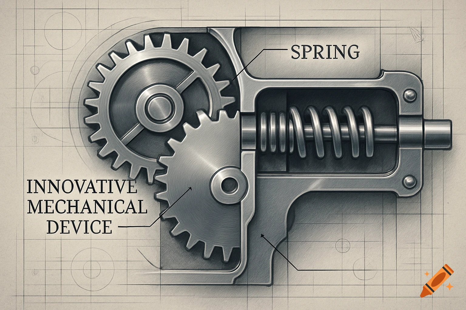
Create a technically correct, mechanically realistic engineering concept of an autonomous EXTERNAL PIPE INSPECTION ROBOT. The robot travels ONLY ON THE OUTSIDE SURFACE of a cylindrical water pipeline. It never enters the pipe. Its purpose is to move along the pipe and inspect the pipe surface for leaks, cracks, corrosion and structural defects. CORE GEOMETRY — FOLLOW THIS EXACTLY: The robot has EXACTLY FOUR WHEELS TOTAL. The robot is divided into TWO CHASSIS SECTIONS: 1. FRONT CHASSIS 2. REAR CHASSIS The front chassis and rear chassis are connected by ONE CENTRAL ARTICULATED JOINT. Each chassis is a rigid transverse frame that surrounds the pipe and carries EXACTLY TWO WHEELS. Therefore: - front chassis = 2 wheels - rear chassis = 2 wheels - total = 4 wheels On EACH chassis, the two wheels are positioned on OPPOSITE SIDES of the cylindrical pipe, approximately 180 degrees apart around the pipe circumference. The wheels are NOT next to each other on the same side. The two wheels on each chassis must grip the pipe from opposite sides. The four wheels must remain in contact with the OUTER cylindrical surface of the pipe. The robot is mechanically clamped around the pipe like a lightweight external crawler. PIPE DIMENSIONS: Main pipe diameter shown in the image: 250 mm. The robot must accommodate a pipe diameter range of 200–300 mm. The diameter adaptation must NOT use complex robotic actuators. Instead, use a simple symmetrical spring-loaded mechanism: - each wheel is mounted Ver mais
More images like this