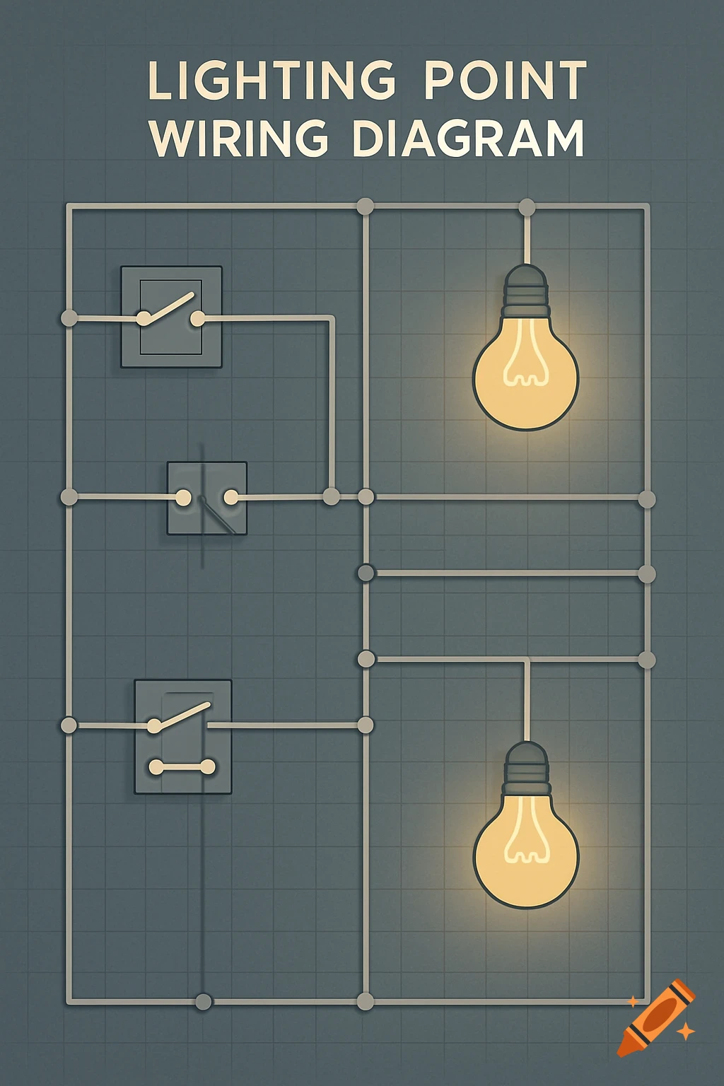
A professional electric guitar wiring diagram showing a 3-way switch, volume, tone potentiometers, pickups, and an output jack.
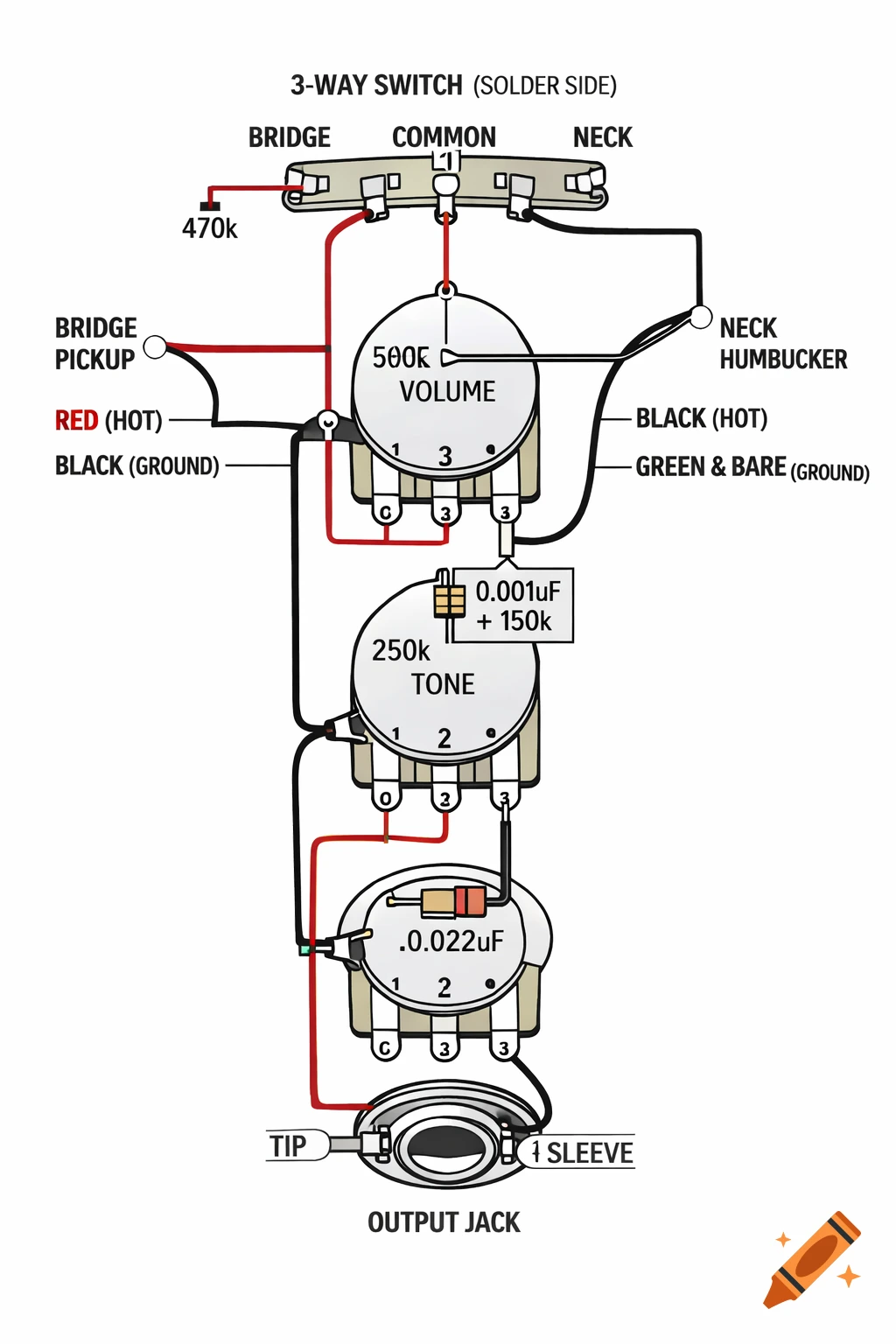
Create a clean professional electric guitar wiring diagram in the exact style of Fender or Seymour Duncan technical manuals. White background. Top-down layout of a Telecaster control plate. Clear black outlines. Flat vector technical illustration. All components labeled in clean sans-serif font. No artistic style, only technical schematic style. Components to include: 1) 3-way blade switch at top (viewed from solder side). Three lugs labeled: - BRIDGE (left) - COMMON (center) - NECK (right) 2) 500k Volume potentiometer in the middle (rear view, 3 lugs facing up). Lugs clearly numbered 1-2-3 from left to right. Lug 3 bent to casing and grounded. 3) 250k Tone potentiometer below volume (rear view). Lugs numbered 1-2-3. Lug 3 grounded to casing. 4) Output jack at bottom with: - TIP - SLEEVE 5) Bridge single coil pickup drawn on left with two wires: - Hot wire to BRIDGE lug of switch - Ground wire to back of Volume pot 6) Neck humbucker (2 conductor) drawn on right: - Black wire (hot) to NECK lug of switch - Green + bare wire to back of Volume pot Wiring connections: - Switch COMMON lug connected to Volume lug 1 - Volume lug 2 connected to Jack TIP - All grounds connected to back of Volume pot (star grounding) - Tone lug 1 connected to Volume lug 2 - 0.022uF capacitor between Tone lug 1 and ground - Treble bleed (0.001uF capacitor + 150k resistor in parallel) between Volume lug 1 and lug 2 - 470k resistor from BRIDGE switch lug to ground Wire colors: - Red = hot signal - Black = Voir plus
More images like this