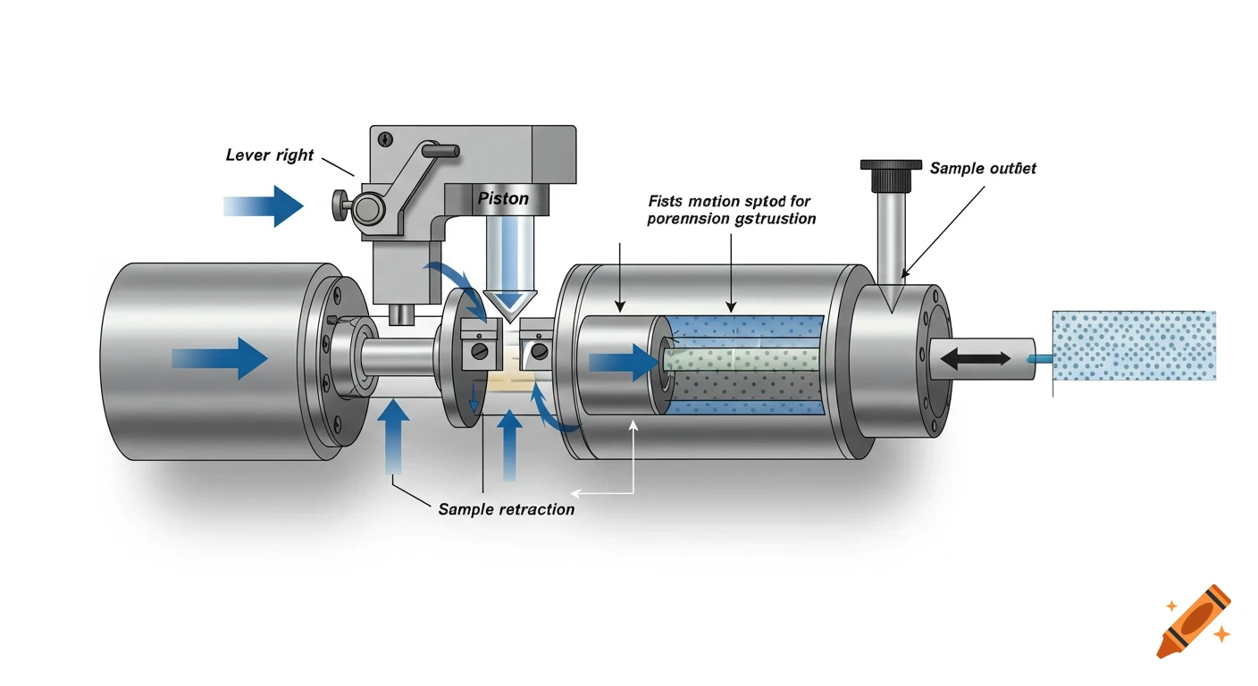
A detailed cross-sectional schematic diagram of a trunnion-mounted ball valve, illustrating various forces like fluid pressure, spring force, friction, and reaction forces.
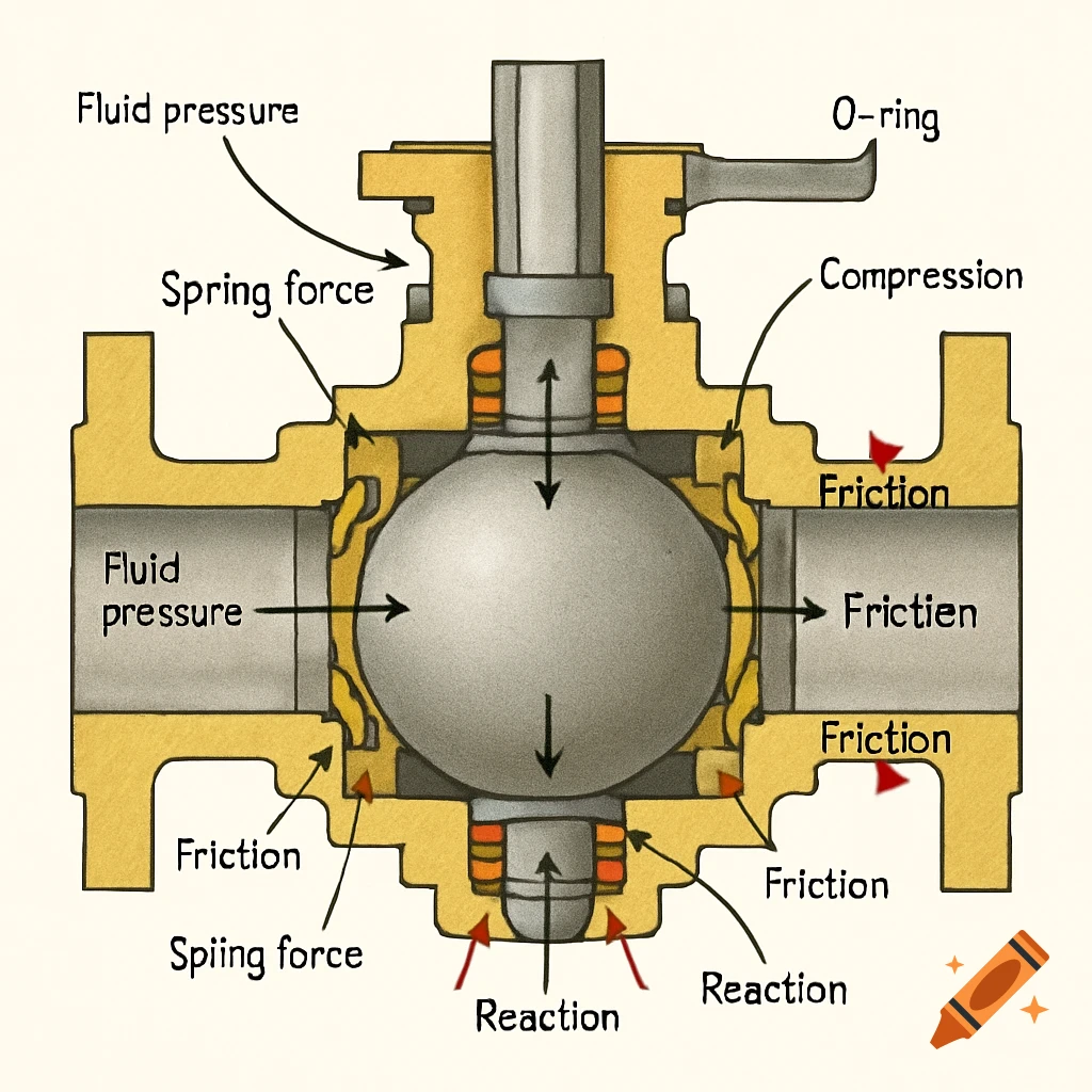
“A detailed cross-sectional schematic diagram of a trunnion-mounted ball valve with Teflon spring-loaded seat rings and O-ring stem seals. The diagram should clearly illustrate the forces acting on the valve components, especially those contributing to the opening torque. Key forces to show include:\n1. Fluid pressure acting on the ball and seat rings (indicated by arrows).\n2. Spring forces behind the seat rings pushing them towards the ball.\n3. Friction forces between the Teflon seat rings and the ball surface (opposing rotation).\n4. Forces acting on the trunnion pins due to ball weight and seat reactions.\n5. Friction forces at the trunnions.\n6. Forces from the O-rings sealing the stem, showing their compression and pressure activation, and the resulting friction on the stem.\n7. Reaction forces at various contact points.\n8. The overall diagram should emphasize the components relevant to torque calculation, providing a clear visual representation of how these forces contribute to the resistance against opening the valve. The valve should be shown in a closed or partially closed state to highlight the forces acting on the seat rings.” Ver más
More images like this