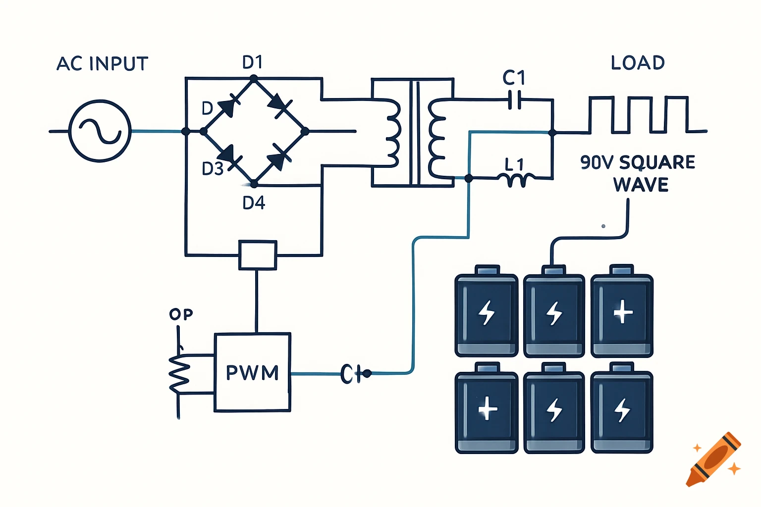
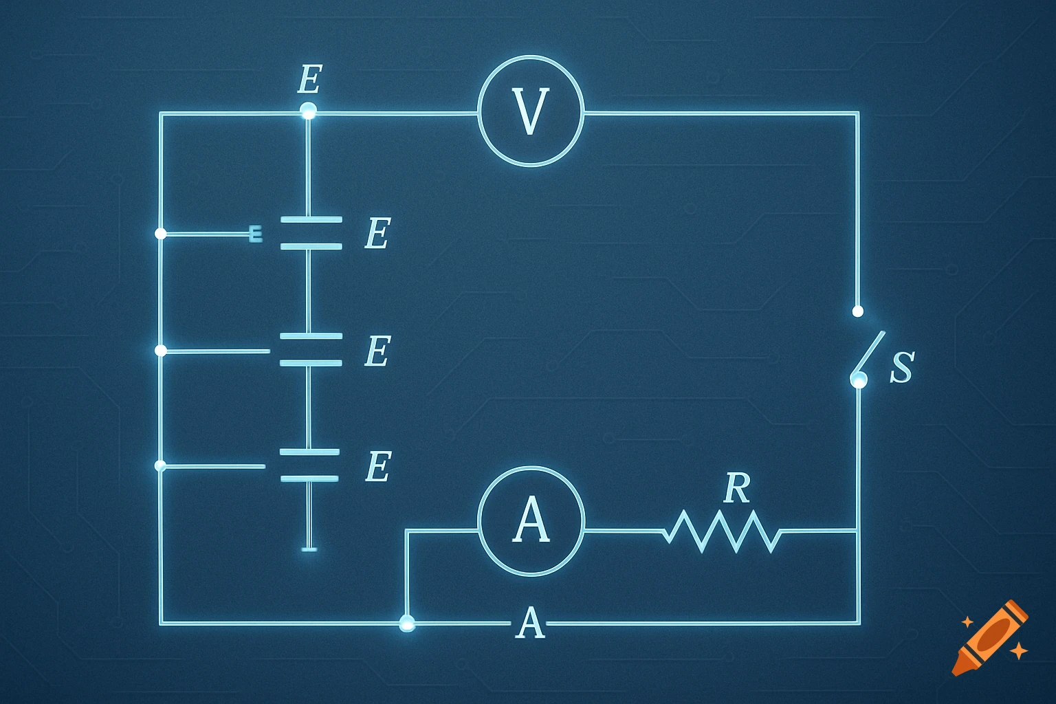
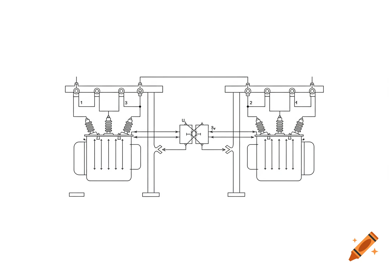
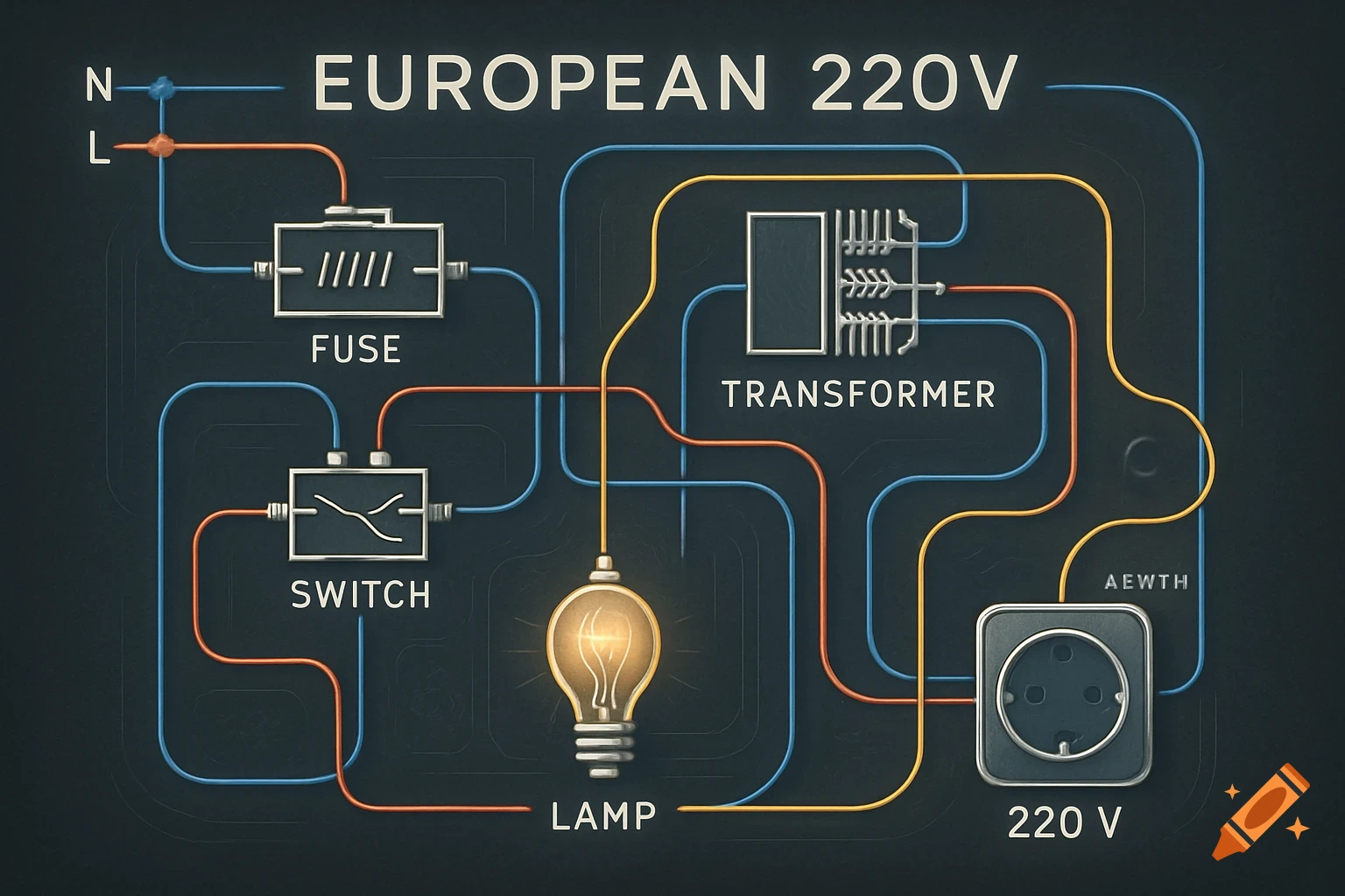
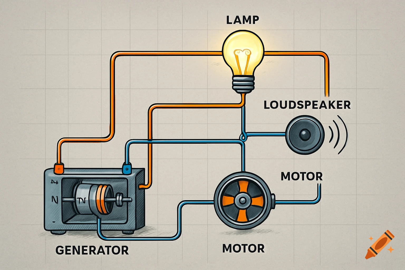
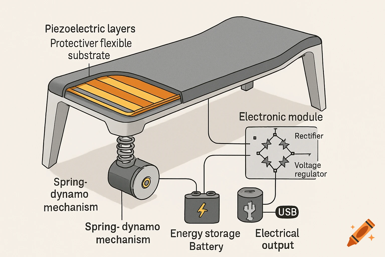
Technical electrical wiring diagram for Shelly 1 Gen4 smart relay connected to a socket and garage door motor.

Professional electrical wiring diagram, ultra-detailed technical schematic, white background, high contrast black lines. CENTER: Shelly 1 Gen4 smart relay module, rectangular blue device (dimensions approx. 42x37x17mm), clearly visible screw terminals on right side labeled from top to bottom: - Terminal L (top, for Live 230V) - Terminal N (second, for Neutral) - Terminal I (third, for potential-free Input) - Terminal O (bottom, for potential-free Output) - Terminal SW (far right, unused in this diagram, mark as "nicht verwendet") LEFT SIDE: European 230V wall socket (Schuko type), three terminals visible: - L (Live, left terminal) - connected via BROWN wire (1.5mm² NYM-J cable) to Shelly terminal L - N (Neutral, right terminal) - connected via BLUE wire (1.5mm² NYM-J cable) to Shelly terminal N - PE (Protective Earth, top terminal, green-yellow stripe) - wire passes through but NOT connected to Shelly (show wire continuing, add label "PE durchverbunden, nicht am Shelly") Add text near socket: "230V STECKDOSE (L/N/PE)" Add text near brown wire: "Braun (L) - 230V Phase" Add text near blue wire: "Blau (N) - Neutralleiter" Add warning symbol ⚠️ near PE wire: "Schutzleiter NICHT am Shelly anschließen!" RIGHT SIDE: NovoPort 2 garage door motor control unit, gray rectangular box (approx. 150x100mm), terminal block visible with labels: - Terminal 1: "230V L" (mark as "NICHT VERWENDEN für Shelly") - Terminal 2: "230V N" (mark as "NICHT VERWENDEN für Shelly") - Terminal 3: "IMPULS +" Ver más
More images like this