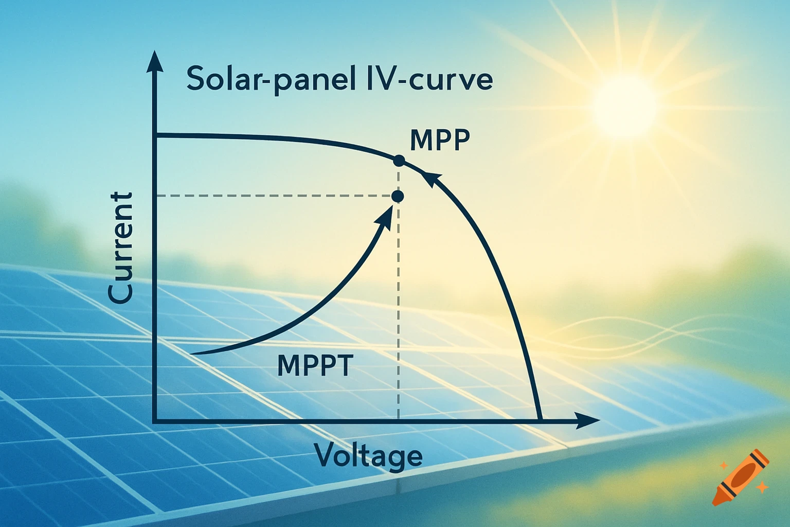
A professional aerospace engineering system-level diagram of a small fixed-wing aircraft, showing control, power, propulsion, actuation, and structural systems with interconnected components via colored lines and arrows.

Create a professional aerospace engineering system-level diagram of a small 3D-printed fixed-wing aircraft. The diagram should follow a clean systems engineering style with clear subsystem grouping, directional arrows, and labeled signal, power, and mechanical flows. Include the following subsystems and components: Control System (left side): Radio Controller → Receiver (wireless communication) Power System (top): Two Batteries in Series → Electronic Speed Controller (ESC) Propulsion System (center): ESC → Brushless Motor → Propeller Actuation System (right): Receiver → Servos → Pinion Gear → Slotted Gear → Wing Spars Structural System (bottom/center): Nose Cone → Electronics Hub → Lock Ring → Center Fuselage Halves → Tail Boom Connector → Tail Boom → Tail Wing Structure (right vertical chain): Spars → Wing Base → Spars + Connectors → Wing Tip Style requirements: Use a minimal color palette (grayscale with subtle blue or green accents for subsystems) Group components into labeled boxes: Power, Control, Propulsion, Actuation, Structure Use different arrow styles: Solid arrows for mechanical connections Dashed arrows for electrical signals Bold arrows for power flow Clean sans-serif engineering font (like CAD or technical diagram style) White background, no gradients Balanced layout with clear left-to-right and top-to-bottom flow Include a small legend explaining arrow types Make it look like a figure from an aerospace systems design report (high clarity, professional, Mehr sehen
More images like this