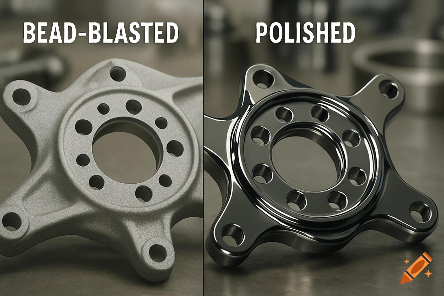
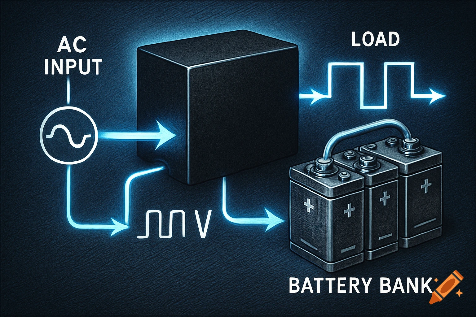
Technical illustration of a lateral-tilt weight-shifting servo mechanism in neutral, 15-degree left, and 15-degree right tilt states.

Generate a high-precision mechanical engineering technical illustration, orthographic view, of a standalone, grounded lateral-tilt weight-shifting servo mechanism assembly. The illustration must side-by-side display the mechanism in three distinct states: Center/Neutral, 15 Degrees Left, and 15 Degrees Right. The core components are isolated; do not generate any robot body or sphere bits. The specific components and their layout are critical: The Grounded Backplate: The mechanism is mounted to a simple, rigid, static metal backplate that serves as the fixed coordinate system. The High-Torque Servo (labeled 'MG996R'): The body of this servo is rigidly bolted (fixed) to the static backplate in a vertical orientation. Its output shaft faces the viewer. The Main Pivot Axle: This is a smooth steel pin, supported by miniature bearings, passing centrally above the servo body, through the grounded backplate. The Tilting Cradle: This is a robust U-shaped cradle (e.g., 3D printed PETG or metal plate). It is centrally balanced and rotates smoothly around the Main Pivot Axle. The Heavy Weight (Battery): A dense, block-shaped Lipo battery pack (like the specific one discussed) is securely held inside the tilting cradle. It is secured by a wide, tight Velcro security strap. The Mechanical Linkage: A standard metal servo horn (arm) is attached to the MG996R output shaft. A rigid metal push-rod (linkage) connects the tip of the servo horn to an offset pivot point on the underside of the Mehr sehen
More images like this