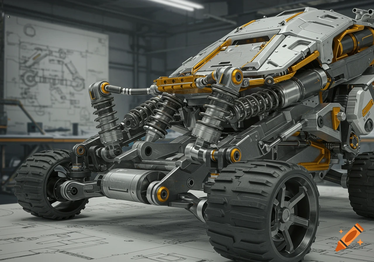
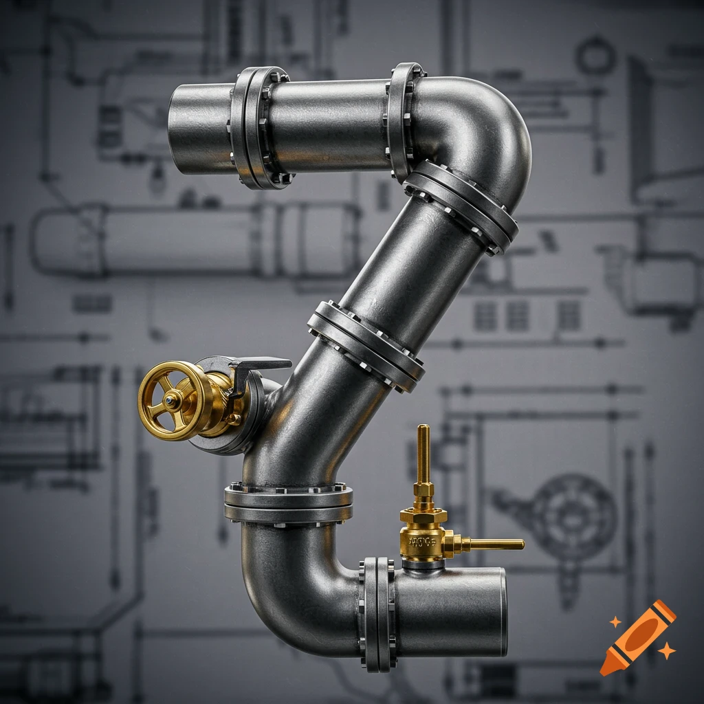
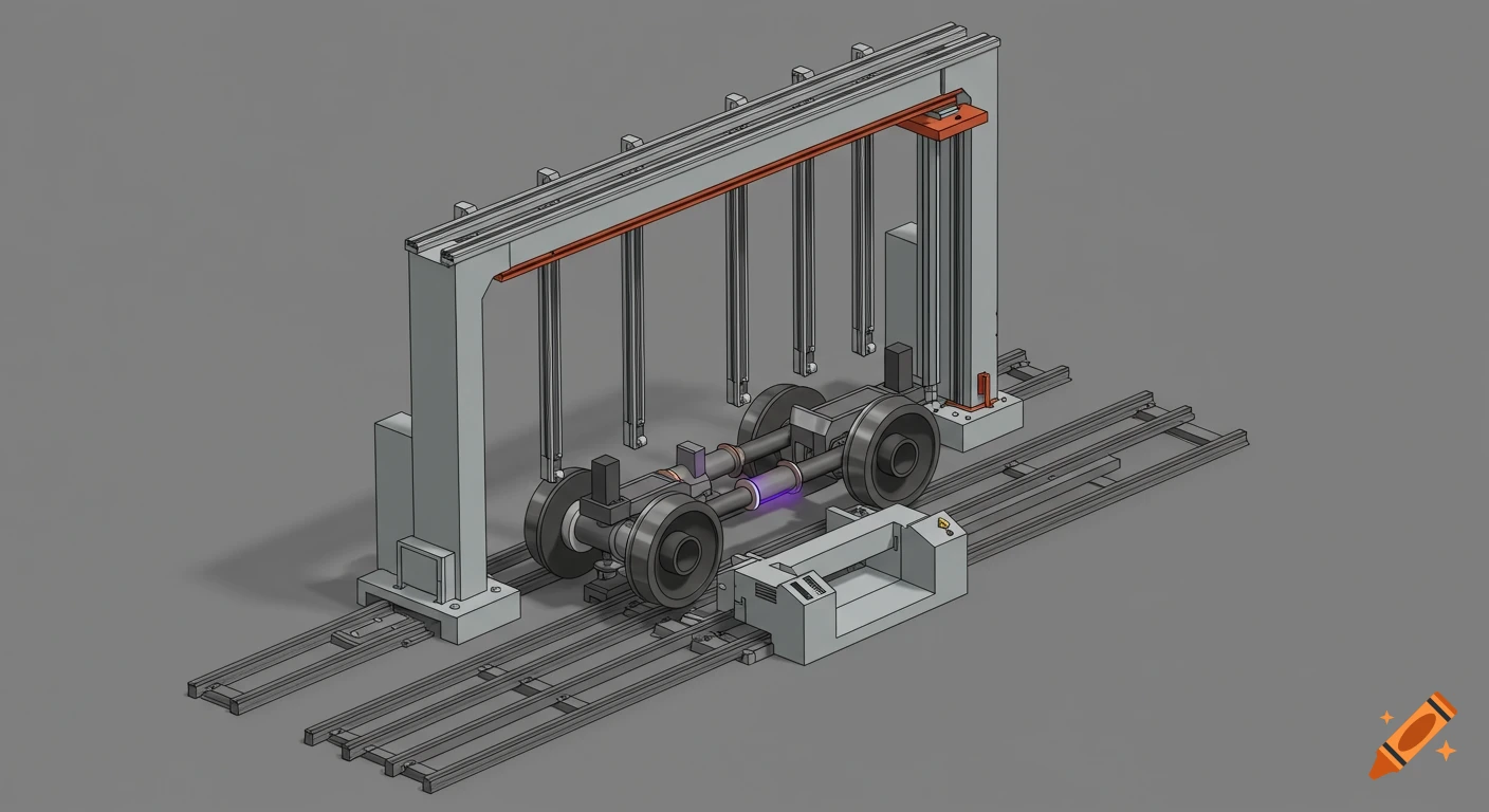
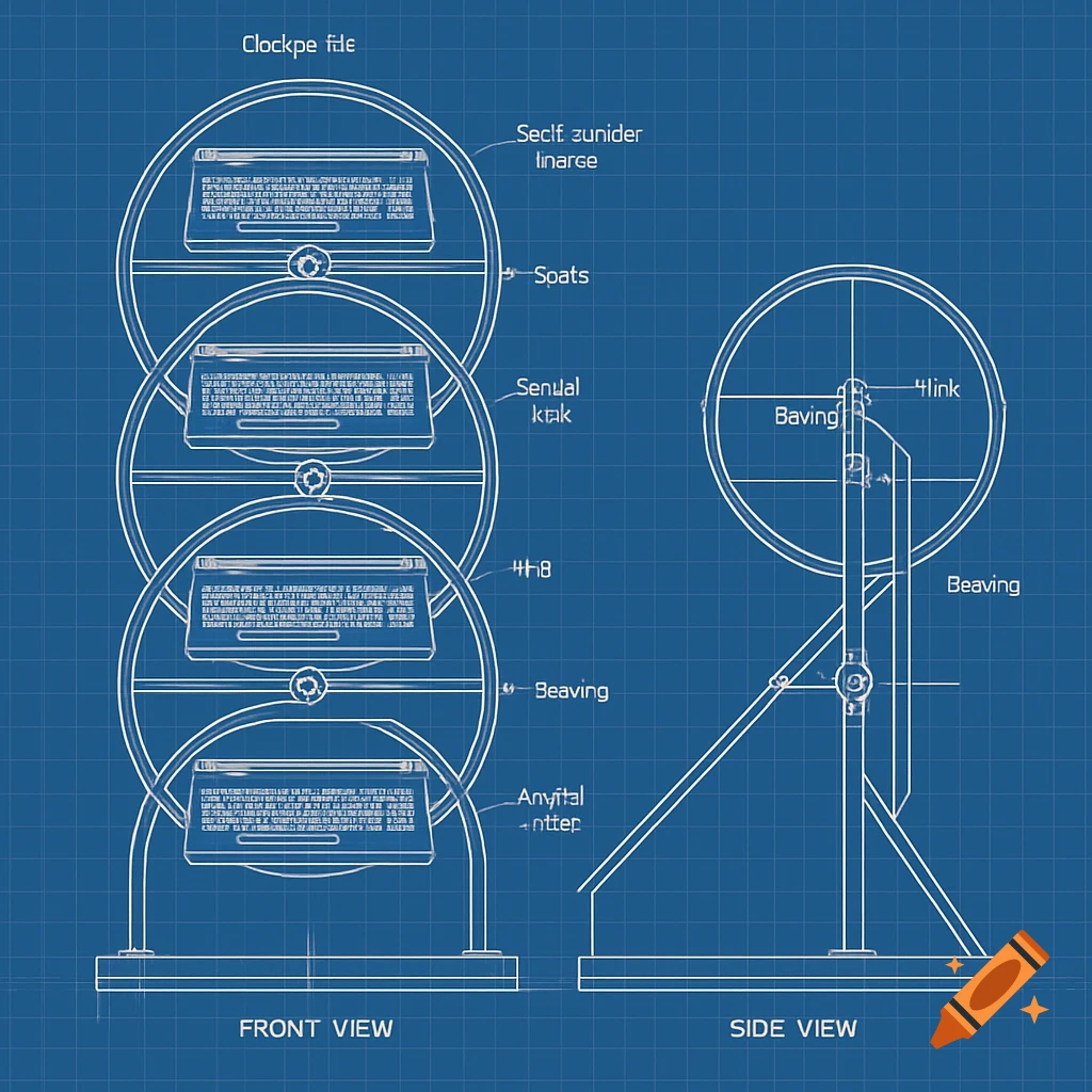
Technical mechanical concept drawing of an external pipe inspection robot clamped around a bend pipeline.

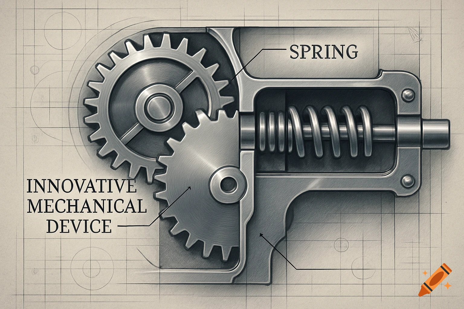
Generate a technical mechanical concept drawing of an external pipe inspection robot. Show the robot clamped around the OUTSIDE of a cylindrical pipe, diameter 250 mm, using exactly FOUR rubber wheels. Use two longitudinal wheel frames positioned on opposite sides of the pipe. Each frame has two wheels aligned along the pipe axis. The left and right wheel frames are connected to a central body by a symmetrical radial spring-loaded mechanism. The mechanism allows both frames to move inward and outward to adapt to pipe diameters from 200 to 300 mm. Each frame has two pivoting suspension arms holding the wheels. The springs provide continuous radial force toward the pipe surface. The robot is divided into a front section and rear section. The two sections are connected by ONE central articulated joint. The front section and rear section can rotate relative to each other so the robot can follow a curved pipe. Show the robot on a 90-degree smooth bend in the pipeline. The front four-wheel geometry and rear four-wheel geometry must follow the local pipe direction while maintaining contact. Important mechanical rules: - exactly four wheels total - wheels arranged around the exterior circumference of the pipe - two wheels on one side, two wheels on the opposite side - all wheels touching the pipe - no wheels inside the pipe - no tracks - no fifth wheel - no unnecessary suspension mechanisms - one central articulation joint - symmetrical clamping mechanism - visible springs and pivot Mehr sehen
More images like this